
The following post talks about the importance of selecting the best antenna and understanding coverage patterns.
In any RF system, the antenna is the radiating element. RF waves are to be propagated through free space, and it is this component that causes this to happen. The antenna device also receives the RF signals from other transmitters. Available in various forms, the antenna results in varied radiation patterns and, therefore, various coverage patterns given the same RF power input. The antennas design impacts the reception of RF signals, in addition to varied radiating patterns.
Key factors when selecting an antenna are the gain of the antenna and the radiating pattern, as well as the frequency range for which the antenna is designed. Antennas should be either 2.4 GHz or 5 GHz antennas in most AP or bridge implementations today. Once you have identified the appropriate frequency band, the appropriate gain and radiating pattern must be selected.
Today, antenna gain is usually listed as dBi and is measured in decibels. This metric is achieved by comparing the antenna’s gain in the intended radiation direction against that of a theoretical isotropic radiator. The isotropic radiator is a theoretical antenna, radiating energy equally in all directions out of the antenna. Whilst it is considered spherical, no such antenna actually exists. For example, the common antenna included with a consumer-grade wireless AP or router is a 2-3 dBi antenna. This simply means that the antenna has 2-3 dB gain in the direction of intended propagation.
A higher gain antenna (for example, 11 dBi as opposed to 2.14 dBi) will radiate a receivable signal further in the intended direction in free space. Of course, indoors there will be reflections and other RF behaviours, so the signal may not radiate as far at acceptable signal levels as it would in free space, but it would still radiate farther than a lower gain antenna.
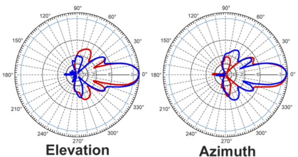
Now, the final part to consider when selecting an antenna is the radiation pattern or simply, the antenna pattern. Antenna charts are the most frequent mode of communication of antenna patterns. The horizontal and vertical radiation patterns of the antenna are shown in the charts.
In the elevation charts, the vertical pattern is shown, and the Azimuth chart shows the horizontal pattern.
Helpful tip! Remember that the elevation chart shows the radiation pattern of antennas as if you are looking at it from the side. The Azimuth chart shows it as if you are looking down on the top of the antenna (assuming the antenna is vertically upright).
Elevation = side view
Azimuth = top view
The following images show each chart type:
Once you’ve got the hang of this information, you can use it to easily select the appropriate antenna for you and understand the different coverage patterns you can expect from them.
London 0203 322 2443 | Cardiff 02920 676 712 | Hampshire 01962 657 390 | [email protected]
https://www.cwnp.com/selecting-best-antenna/