People Tracking technologies measure where people are and how long they stay in a specific location – The physical store.
The tracking solutions measure demand, service, and customer engagement in location and time-based metrics. They optimize demand forecasts, location marketing, scheduling, queues, and sales operations. And they empower the retailers to be more productive and profitable.
Why Care About Tracking People?
Ask what is the biggest challenge in retail, and the answer is seamless analytics. People Tracking Technologies offer the ability to manage the physical store with data.
People Tracking is the core of Location Analytics, InStore Analytics, and Behavior Analytics. Whatever term you may use, the solution tracks the person by location, and per period of time.
In Location Analytics, we measure customer engagement in zones and displays. In People Counting, we detect the number of people entering and exiting the store. In Queue Management, we predict how many cashiers should be active to prevent queues. In Labor Analytics, we optimize the schedule. And InStore Analytics covers the realm of all systems pertaining to the physical store.
Regardless of providers, the criteria to choosing a tracking solution is the business value. The benefits depend on the behaviors you are trying to change.
Tracking versus People Counting
People Tracking includes the detection, recognition, and tracking of objects. The solution may also include machine learning and advanced analytics.
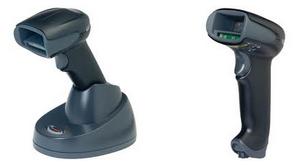
People Counting. The term refers to detection tech that “counts” people. The technologies include Time of Flight, Infrared Beams, Thermal Imaging, and Video Analytics.
The data output is In/Out counts. The common deployment is door-counters, and other “crossing the line” scenarios. And the primary business benefit is the calculation of Sales Conversion.
Image Recognition. There are different levels of imaging technologies from facial recognition to detecting heads. Besides people tracking, we deploy the tech in driverless cars and Facebook Ads.
People Tracking. Tracking refers to objects in motion. Once we have detected an object, and recognized it as a “person”, the next step is tracking. The focus is on measuring the path of the person.
Tracking demands Good Enough Accuracy. Besides over-counting and under-counting, we have switching and precision errors. This is why tracking data often comes from wireless devices instead of sensors. It’s easier to track individuals by their smartphone signals.
Location Analytics refers to both people counting and tracking technologies. The term implies the solution provider offers both sensor and device-based tracking for a complete analysis of the store (see below).
ABI Research estimates that People Counting will transform to $3Billion market by 2018. Location-Based Services will grow above $62 Billion.
Sensor vs. Device-Based Solutions
Sensors include video, thermal, and laser technologies. In wireless tech such as WiFi, GPS and BLE, we track the device. Sensors and Device-Based are often complementary solutions. And each technology has its own challenges and benefits. In sensors, we care about accuracy. The wireless technologies are distinct by their range.
The differences are not only in technology. BLE Beacons primary goal is to send push notifications (Location Marketing). Wi-Fi tracks the device across great distances. We use mobile application to calibrate tracking with Magnetic Resonance. The 3D Video sensors manage complex frontline queues. And Vision Analytics is a core technology for driverless cars.
There is also the factor of data integration. The connectivity between various store systems, in real time, is complex. Moreover, each technology has its own concepts of consistency and validation.
Note on Analytics: Two important factors to remember. First, the data from device-based tracking is a sample of individual behaviors. Thus metrics such as conversion rate requires statistics. And second, predictive analytics is important in tracking. Thus the expertise in advanced analytics is a factor in tracking solutions.
Good Enough Accuracy is the key to assessing the business value of a tracking technology.
The Technologies to Track People
The market for people tracking changes as fast as these words are written. We offer no preference for a technology or a solution provider. In 2015, there were 7 technologies. In 2017, we have 12.
Below is a brief summary of selected people tracking technologies.
Vision Analytics
Vision Analytics works by recognizing patterns in images. The AI software translates the images to data, context, and action. The output is not the image, but the description of the picture.
The technology claim to fame was when the Standford Vision Lab program recognized a cat. The technology is a core component in driverless cars and deep-learning imaging. With startups such as Modcam and Seematics, Vision is an emerging technology for retail’s InStore Analytics.
3D Stereo Video Analytics
Stereo sensors are designed for accuracy. They combine high-resolution camera and processor for three-dimensional view of the object. The empiric data on height, mass, speed, and direction, enhances accuracy of the count. Since sunlight and shadows do not have depth, the technology filter them out of the counts.
This architecture allows for tracking objects, over a period of time. It allows for accuracy in high traffic and for complex behaviors. 3D Video Sensors are the preferred choice for frontline queue management.
Leading solution providers include Brickstream, Xovis, Hella, and ShopperTrak (Tyco Retail).
Monocular Video Analytics
Monocular sensors capture images through a single lens camera. The sensor process the image and the output is the data counts.
In door-counting, monocular devices achieve 90% accuracy in 90% of the stores. The challenge of monocular devices is their treatment of depth. The real-time images are compared to a baseline picture. And thus shadows and light impair the counting. Some solutions compare and “fix” the data to a trend, which happens during the upload to the central server.
Since single lens trackers are accurate for most door-counting, they are wide spread. We can find video analytics in smart cameras from Axis to Panasonic.
Thermal Imaging
Thermal Imaging detects emissions from moving objects. Since thermal technology is not sensitive to light, it can function in any physical space.
The accuracy challenge is the “blending” of a person’s heat signature for standing in the same place. In most situations, thermal sensors achieve 95% accuracy rates. And they are easy to install and calibrate.
Thermal sensors are versatile and wide spread. The global leading provider, Irisys, claims over 400,000 sensors installed.
Infrared Beams
Infrared Beams count when a person crosses the doorway and “cuts” the beam. The pros are low cost and simplicity. Because the sensors can be mounted in gateways, they are widely deployed .
The cons is accuracy. The sensors cannot recognize the direction of motion. They also have trouble differentiating between one or more people. Moreover, the system over-counts and under-counts with no data consistency. Thus the data is not recommended by professional data analysts.
Time of Flight
Time of Flight detects the time of light between the camera and the object. By sending the laser beams to many directions, the sensor knows the exact positioning of objects.
The laser sensors are accurate and cost effective. The expertise in laser will allow companies such as BEA Helma to embed people counting directly into door sensors.
Kinect is also a sensor that detects people in motion. The video camera, depth detector, and multi-array microphone generate a three-dimensional image of objects within the field of view. The camera also detects body-type and facial features. Kinect can distinguish objects’ depth within 1 centimeter and their height and width within 3 mm.
Structured Light
Structured Light projects a known pattern on a scene. The array of lights strike the surface allowing the tracker to calculate the depth and the surface of the object. People Tracking comes from 3D Scanners.
Apple, Amazon, and Orbbec are among the companies to deploy Structured Light.
Raspberry Pi Tracking
Open Source Raspberry Pi can be adapted as a motion tracker. This is a low cost solution, but one challenged with support and accuracy.
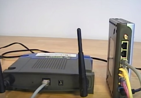
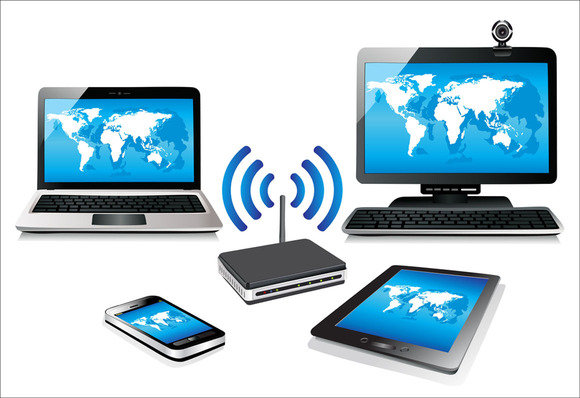
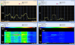
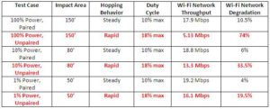
WiFi Location Analytics
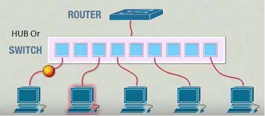
WiFi is a standard for exchanging data over a Wireless Local Area Network (WLAN). The antennas capture radio waves from mobile phones, and can cover a range of up to 100,000 square feet.
Since the MAC Address is unique per device, the system tracks a customer from entry to exiting the store. It can even track people beyond the store for Proximity Traffic.
The dependency on the customer’s activation of WiFi limits the data output to a sample out of the total population. But the tech is ideal for unstructured motion and large venues such as airports and stadiums.
WiFi suffers from the challenges of location accuracy. It depends on Cellular Tower Triangulation, ranging from one meter to half-mile. And by nature, the data output is a sample of behaviors. But the low costs and ease of setup, make WiFi Tracking an attractive proposition.
Leading solution providers include Euclid Analytics and Cisco Meraki.
Bluetooth Low Energy Beacons
Beacons are transmitters of Bluetooth Low Energy (BLE) radio waves signals. BLE functions in the range between NFC and GPS. The devices work indoors, which makes it ideal for communicating with customers.
Beacons allow the customer’s application to find if it is close (in proximity) to a specific location such as display or aisle. Beacons are the favorite tech for Location Marketing.
Beacons face three challenges: First, the layers of security require a series of opt-in. Second, due to privacy concerns many customers shy the retailer’s application. And third, WiFi/GPS technologies are improving fast to work indoors.
The beacons ecosystem includes the Google Eddystone and Apple iBeacon platforms. It also includes Location Marketing such as Swirl and InMarket.
GPS Location Analytics
GPS Tracking comes from the Global Positioning System, a network of orbiting satellites. GPS receivers are now built in the Apple and Android operating platforms.
The best known application of Location Analytics is Google Store Visits. The data is an outcome of Location Marketing. By 2017, Google Ads reached 5 Billion location-based advertising. Using Geo-Marketing to drive footfall traffic to the physical store is a key trend per Mary Meeker Internet’s Trends.
3D Spatial Learning (Augmented Reality)
Augmented Reality will probably be the technology of Retail Future. Remember Pokemon Go. Then came Amazon Go. But first was Google’s Project Tango. You can see the future in Gap’s foray into AR Dressing Rooms.
Augmented Reality uses computer vision to enable mobile devices to detect their position relative to the world around them without using GPS, WiFi or other external signal. In essence, vision technology emulates our ability to manipulate three-dimensional objects.
Location Analytics
Location Analytics refers to the ability to gain business insights from knowing where people are. Location Analytics providers offer a wide variety of people tracking technologies, solutions, and services. The big companies such as ShopperTrak (Tyco Retail), RetailNext, and Ipsos Retail have global reach.
Vibrant regional companies include Vizualized in Hong Kong, Headcount Systems from Canada, Savant Systems in Dubai, and Intelligenxia in Chile.
Added to Location Analytics, some offer Location Marketing. Since marketing agencies are data-oriented, they push to infuse analytics in the store. This led to partnerships between agencies and vendors. It also encouraged the rise of marketing/data savvy retail executives.
Big software companies such as IBM, Microsoft, and Intel are also interested in the physical store. They are creating massive ecosystems of end points and advanced analytics. As a result, Location Analytics is being embedded into the Internet of Things.
Bringing It All Together
People Tracking Technologies offers all retailers the ability to manage the physical store with actual data. With behavior-based seamless analytics, we can optimize each step in the InStore Funnel. This is the secret to fast growth, and profitability.
12 Technologies to Track People